Frequently asked questions in Night Vision
What is Night Vision?
Night vision enables to operate safely in night and low light conditions. Owning the best night vision equipment alone will not provide the best images. That's why it is important to opt for a high-quality image intensifier tube (IIT) to have the best possible performance.
Over the years, night vision has become a key opto-electric technology in modern warfare as more and more operations take place by night. Photonis offers a wide range of intensifier tubes, enabling users to find the one that will work for their specific mission or operational requirement.
What is an Image Intensifier Tube (IIT)?
An IIT is a module that intensifies, or amplifies, low light level images into levels that can be seen by the human eye. The IIT collects the existing ambient light from natural sources, such as starlight or moonlight, or from artificial sources such as street lights or infrared illuminators. The light passes through several internal components to be multiplied several thousand times, producing a much brighter image that can be seen by the soldier through the night vision device.
How does an image intensifier work?
First of all, photons (light) are converted into electrons by the photocathode. Then, they are accelerated through an electrical field and hit the microchannel plate walls to generate secondary electrons that in turn will generate more electrons into what is called an « electron avalanche ». Then, multiplied secondary electrons are accelerated through an electrical field, hit the phosphor screen layer and are converted back into light. Finally, the image is projected through the eye-piece of the night vision device.
What is the difference between night vision and infrared products?
Night vision is the ability to operate safely in night or in any environment under low light conditions. Whereas, infrared imaging products, such as thermal (LWIR) or Shortwave Infrared (SWIR) sensors, are optimized for day-through-night lighting conditions and support surveillance & security applications, industry & research projects, and mobile use.
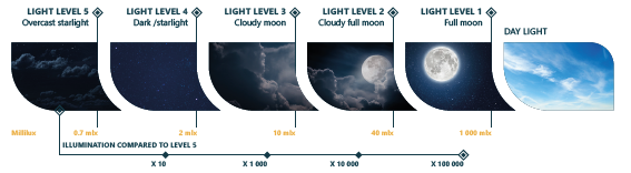
What are the different light levels?
In night vision, we have defined 5 different light levels from 1 (full moon) to level 5 (overcast starlight) The better the image intensifier tube, the better the image quality in low light conditions.
Where are the image intensifier tubes produced?
Photonis image intensifier tubes are made in Europe (Brive-La-Gaillarde, in France and Roden, in the Netherlands). That’s why they are ITAR free: The International Traffic in Arms Regulations (ITAR) is a set of U.S. federal government regulations used to control the import and export of objects and services related to national defense.
IIT for which equipment? Which equipment is the image intensifier tube dedicated to?
Photonis offers the highest quality of image intensifier tubes for a wide range of night vision devices which support specific requirements, environments, applications and missions: binocular goggle, monocular goggle, panoramic goggle, clip-on weapon sights, etc.
What about the size and the weight?
Reducing the load on a soldier is a constant challenge. We can notice a real evolution concerning the size and weight of our image intensifier tubes (IIT). We talk about SWaP: Size Weight and Power.
Reduction of SWaP contributes to enhance the efficiency and effectiveness of armed forces. Night vision devices that are designed around the 16mm IIT offer the tremendous advantage of having the same level of performance as those based upon the 18 mm tube, but with significantly reduced weight.
What could damage the Image Intensifier Tube (IIT)?
The IIT is sensitive to light if you expose this device to daylight such as sunlight, but also cloudy skies or direct light such as car headlights. So you will damage the night vision system. More especially, using an IIT when bright light hits the photocathode might seriously damage the photocathode itself. The key to avoid any damage it’s to systematically cover the night vision device (NVD) with their protective caps even if the NVD is off, raised on the helmet.
What are black spots?
Black spots are cosmetic blemishes that may originate from fixed tiny particles inside the Image Intensifier Tube (IIT) or in the fiber optic of the screen. Small size black spots are inherent to the manufacturing process and do not affect the performance or reliability of the device. Black spots can be acceptable as long as they don’t interfere with the viewing of the image to be observed and therefore specifications of tubes should be fine-tuned to match the constraints of the end-use application.
White or green phosphor screen?
The phosphor screen of the Image Intensifier Tube (IIT) converts the electron avalanche from the microchannel plate back into photons, resulting in the green image that has become the signature view in night vision technology.
White phosphor, or P45, provides excellent recognition and has similar decay time properties as the P43 (green) phosphor. In night vision, there are no « lab » performance differences between P43 & P45. Furthermore, during trial of soldiers, no combat effectiveness difference was found. That’s why phosphor color is often a personal preference, the most important criteria being for the operator to have as less eye fatigue as possible.
What is the FOM?
In military applications, Night Vision Devices (NVD) are developed with the ability to provide a clear image thanks to the contribution of light coming from external sources such as stars, moon or artificial light of the cities. While choosing NVDs, a lot of important performance parameters need to be considered and particularly the FOM because it is used to determine the overall performance of the Image Intensifier Tube (IIT) and is calculated as a product of the IIT resolution by the Signal-to-Noise Ratio (SNR).
- The SNR typically defines how much system noise interferes with the image.
- Limiting resolution measured in line pairs per mm (lp/mm) refers to contrast allowing to gives more details
What is the Gain?
Gain, also referring to brightness gain or luminance gain, is defined as the number of times the image intensifier tube amplifies the light. This characteristic should match the Night Vision Device (NVD) into which it is integrated. Providing a NVD with an External Gain Control (EGAC) allows the user to have a more versatile system, this allows him to dim the brightness.
What is Auto-Gating (ATG)?
Auto-Gating provides a better reaction time when sudden bright light events occur, such as explosions or car headlights. The benefits can easily be seen not only during day-night-day transitions, but also under dynamic light conditions when rapidly changing from low light to high light conditions, such as sudden illumination of dark room or shooting at night (muzzleflash).
The ATG maintains the optimum performance of the Image Intensifier Tube (IIT) while continuously revealing mission critical details, safeguarding the IIT from additional damage and protecting the user from temporary blindness.
Frequently asked questions in Nuclear
What determines usable life in a detector?
A detector is usable so long as it remains sensitive to neutrons and capable of transmitting sufficient signal to be used by the electronics. The sensitivity of the detector will gradually decrease over time as it is exposed to thermal neutron flux, and the detector will remain viable as long as the electronics allow for the decrease in sensitivity. For B-10 lined proportional counters the gas internal to the detector is vital to linear performance of the detector and is subject to degradation during operation in high radiation environments. Photonis proportional counters may include an additional reservoir of proportional gas which extends detector life (up to ~5 x 10¹⁸ n/cm2) substantially, making total lifetime greater than the life of similar detectors without this reservoir and significantly longer than BF3 counters.
What role does temperature play in detector operation?
Detector operation can be significantly affected as the ambient temperature they are exposed to increases above 400 C, by several different mechanisms. The internal gases used to ensure linear operation of the detector must be carefully chosen to ensure they can remain chemically unchanged at these high temperatures. Further, as temperature rises above 400 C the internal resistance of the detector may decrease, causing a rise in leakage current which could limit the functional range or decrease the accuracy of the detector. For these concerns Photonis has designed high temperature detectors, utilizing the appropriate gases, materials, and guard ring construction to allow accurate and reliable operation up to 600 C.
What are the differences between a thermal and fast neutron detector? Why might I use one or the other?
‘thermal’ and ‘fast’ refer to the energy level of the neutron incident on a detector. Thermal neutrons are typically defined as having energy <.025 eV. These lower energy neutrons are more likely to be absorbed by neutron sensitive materials, meaning thermal neutron detectors tend to have higher overall sensitivity. Thermal neutron detectors are designed to generate the majority of their usable signal from interactions with thermal neutrons, where fast neutron detectors are primarily capable of measuring high energy neutrons (>1 MeV). This has applications for research, where it may be important to use multiple detectors to differentiate between neutron energies, or in reactor applications where measurable neutron flux is primarily in high energy neutrons.
Why use a B-10 lined proportional counter vs. a fission chamber for neutron detection?
Each detector type offers unique characteristics which suit it to a particular application. B-10 lined proportional counters offer excellent sensitivity to thermal neutrons, allowing them to achieve sufficient count rates in low neutron fluxes. For example, this feature makes the use of B-10 proportional counters attractive as monitors during initial reactor criticality, where the increased detector sensitivity ensures that smaller, less expensive, start-up sources can be installed in the reactor core. Fission chambers, in contrast, have lower sensitivity to thermal neutrons but have superior resistance to gamma ray interference and offer the capability to operate over many decades of neutron flux. This feature makes fission chambers the ideal choice as wide range monitors of reactor power. The Photonis technical team is happy to work with customers to determine which detector type makes the most sense in each customer application.
Why do some detectors include integrated mineral insulated cabling instead of a standard connector?
Integrating a long mineral insulated cable with the body of the detector is ideal for the severe operating environments (high radiation level, humidity, vibration, high temperature) to maximize reliability and life of the instrument. Photonis recommend the use of integral cable for nuclear power applications to ensure trouble-free long-term operation. In mild environments, or in applications which otherwise do not permit integral cabling, Photonis is able to offer detectors with connection directly at the connector body.
What difference is there between coaxial and triaxial cables? How will I know which is best for my application?
Triaxial cables provide additional screening against unwanted sources of noise compared to coaxial cables- EMI/RFI interference and potential ground loops for small signals can be minimized, although this comes at a trade-off more difficult mechanical construction, lead-time, and cost. Typically, coaxial cables are sufficient for most nuclear applications but unusual, demanding, or unique applications may require the use of a triaxial cable solution. The Photonis Nuclear Instrumentation team has experience both working with our clients in determining the correct cable solution and qualifying the solution for use in industry.
Frequently asked questions in Detection for Analytical Science
How do Vacuum Tube-Based Detectors Work?
Vacuum tube-based Image Intensifier tubes consist of several essential components; a Photocathode, a Microchannel Plate (MCP) and an anode. These components work together to amplify input signal, creating a rich and dynamic output.
In the first step, existing ambient light passes through a photocathode, which converts the incoming photon signal into a photo-electron.
In the second step, photoelectrons are drawn by an electrical field into the MCP where they impinge multiple times on the inner walls and thereby multiply several thousands of times. In photon counting applications the multiplied electron signal is detected using an anode. In the instance of photon imaging applications, the anode converts the electron back into photons to produce an image.
What are the Main Benefits of Vacuum Tube-Based Detectors?
Vacuum tube-based single photon detectors offer several benefits for single photon detection applications compared to other technologies. Here are some of the main advantages:
- High sensitivity: Vacuum tube-based detectors are capable of detecting extremely low levels of light, down to the single photon level. This makes them well-suited for applications that require high sensitivity, such as quantum optics, fluorescence spectroscopy, and low-light imaging.
Wide spectral range: Vacuum tube detectors have a wide spectral response range, spanning from ultraviolet (UV) to near-infrared (NIR) wavelengths. This versatility allows them to be used in a broad range of applications across different scientific disciplines.
Fast response time: MCP-PMTs have fast response times, typically in the sub-nanosecond range. This enables them to accurately capture fast events or rapidly changing light signals, making them suitable for time-resolved measurements and applications requiring high temporal resolution.
Large active area: MCP-PMTs have relatively large active areas compared to other single photon detectors. This makes them capable of detecting photons over a larger spatial area, which is advantageous for applications such as imaging and light detection in broad fields of view.
Low noise: Vacuum tube-based detectors exhibit low noise characteristics, allowing for excellent signal-to-noise ratios. This is especially important for detecting weak light signals and enhancing the accuracy of measurements.
High gain: MCP-PMTs provide high gain amplification due to their electron multiplication stages. Each photon that enters the detector can generate a cascade of electrons, resulting in a significantly amplified output signal. This high gain makes it easier to detect and measure single photons with improved signal quality.
Versatility: Vacuum tube-based detectors can be used in a wide range of experimental setups and configurations, including single photon counting, photon correlation spectroscopy, fluorescence lifetime measurements, and many others. They are adaptable to different experimental requirements and can be integrated into various optical systems.
What are the Main Challenges in Single Photon Detection?
The main challenges in single photon detection include:
- Detection efficiency: The detection efficiency refers to the probability of a photon being detected by the detector. Achieving high detection efficiency is crucial in single photon detection applications. The efficiency depends on factors such as the detector technology, photon wavelength, and optical coupling efficiency. Maximizing detection efficiency is essential for capturing the highest possible number of photons.
- Timing resolution: Many applications involving single photon detection require precise timing information, such as in time-correlated single photon counting (TCSPC) or quantum cryptography. Achieving high timing resolution is challenging, as it requires fast electronics and detectors with short response times to accurately capture the arrival times of individual photons.
- Spatial resolution
- Spectral resolution
- Environmental and operating conditions
- Integration and scalability: In some applications, there is a need for miniaturized or integrated single photon detectors. Challenges arise in developing compact, robust, and efficient detector designs that can be integrated into complex systems or small-scale devices while maintaining high performance.
What Impacts the Detection Efficiency of Single Photon Detectors?
Quantum Efficiency (QE) is a key objective in the development of single photon detectors, as it directly impacts the overall performance of the device.
What are the Limitations of Current Single Photon Detection Technologies?
Current single photon detection technologies often struggle to achieve high performance across all relevant metrics, such as sensitivity, timing resolution, spatial resolution, and spectral resolution, without compromising on other aspects of detector performance.
What are the Potential Applications of Single Photon Detection in the Future?
Single photon detection has potential applications in a wide range of fields, including quantum communication and computing, biomedical imaging, LIDAR, astronomy, and remote sensing.
How do Researchers Plan to Overcome these Technical Challenges?
Researchers are exploring novel materials, device architectures, and fabrication techniques to address the technical challenges in single photon detection. This includes the development of new materials, such as 2D materials or perovskites, improved detector designs, advanced signal processing algorithms, and innovative cooling and shielding techniques. By pushing the boundaries of what is possible in single photon detection, researchers aim to unlock the full potential of this groundbreaking technology for a wide range of scientific and industrial applications.
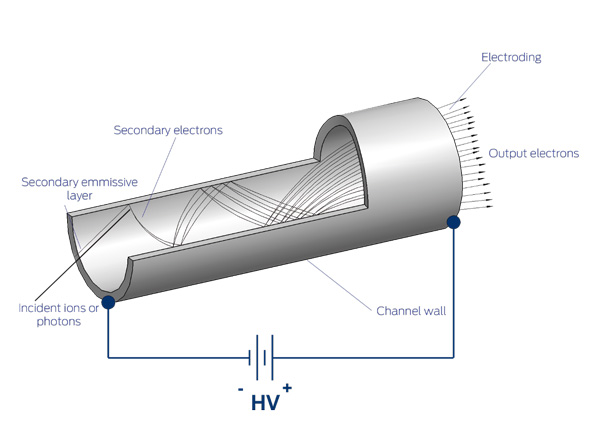
How Does a Channeltron Work?
A Channeltron is an electron multiplier that is comprised of a hollow, semiconductive glass “channel” which has an ability to conduct (or transmit) electricity. Channel electron multipliers directly detect and amplify energetic photons and charged particles such as positive and negative ions, electrons and assorted molecular and subatomic particles. When an ion strikes the input face of the device, it causes the electrons on the outermost area of the atom to be released, causing a secondary electron emission. The number of secondary electrons released depends on several factors, such as the type of particle, the angle at which it strikes the surface, and the energy and characteristics of the surface that is struck. These electrons are then accelerated down the channel by a positive bias current which continues to produce additional secondary electron emissions (and so on) until, at the output end of a pulse of 107 to 108 electrons emerges.
The diagram below provides a visual representation of the working principle of Channeltron operation:
Photonis is the pioneer of Channeltron® Electron Multiplier technology, we possess the knowledge and expertise to recommend the ideal detector for your instrument. For years, customers have been using Channeltrons® because of their superior ability to provide the most accurate analysis. Find out why Channeltrons® are the premium choice among instrument manufacturers.
Why choose genuine Channeltron detector?
If you want a true Channeltron® Electron Multiplier, you must come to Photonis. As the original manufacturer of these products, we have the experience and knowledge necessary to recommend the right detector for your instrument. For years, customers have been using Channeltrons® because of their superior ability to provide the most accurate analysis. Find out why Channeltrons® are considered to be the premium choice among instrument manufacturers.
Optimizing the performance of your mass spectrometer
The performance of your mass spectrometer is often limited by the capabilities of the detector. Photonis developed an electron multiplier family called the MAGNUM™, which provides significantly improved performance by increasing linear output current, reducing noise, and increasing detector life.
Read paper:
Improved Lifetime and Performance for your Mass Spectrometer
Frequently asked questions in Advanced imaging solutions
Does a thermal camera measure the true temperature of an object?
A thermal infrared camera measures a quantity called radiometric temperature by interpreting the infrared radiation emitted from the surface of objects within the scene. Each object is modeled as a blackbody with a unitary, spectrally flat emissivity profile that emits radiation only according to its temperature. Real objects do not have a unitary emissivity value and in fact, most materials have spectrally varying emissivity profiles. Additionally, the thermal radiation from objects within the scene entering the camera is modified by the transmission properties of the intervening atmosphere. In order to convert the radiometric temperature measured by an infrared camera to the true thermodynamic temperature of an object, it is necessary to compensate for both the true material emissivity and atmospheric transmission properties.
For this purpose, Telops provides a user-friendly compensation toolbox as part of its standard software suite.
How does Telops blackbody-free permanent radiometric calibration work?
Typically, infrared cameras are factory-calibrated using high-precision blackbody reference sources to implement a non-uniformity correction (NUC) for improved image quality and a radiometric calibration to relate observed detector response (digital counts) to blackbody temperature for a single exposure time. If the experiment requires temperature measurements at other exposure time values additional calibration data sets must be acquired, a time-consuming and tedious process.
The Telops proprietary permanent radiometric calibration operates its magic by measuring the electron flux generated by the detector (obtained from dividing digital counts by the exposure time) as a function of a blackbody temperature filling the camera’s Field Of View. The flux generated by the detector is independent of the exposure time and as such, this calibration strategy supports a wide range of operating parameters without the need for sporadic or periodic recalibration. All Telops high-speed broadband and multispectral imagers are delivered with this permanent calibration fully implemented and are ready to use from power-on.
With this technique, a Telops camera is permanently calibrated:
- For the whole range of the camera operating temperature;
- For the whole range of target temperature, from – 40 °C to + 2 500 °C;
- For the whole range of exposure time, continuously and without gaps.
This unique calibration allows the user to operate the IR camera with Automatic Exposure Control (AEC). The camera self-adjusts the exposure time of all pixels simultaneously, in real time, to always maximize the signal to noise ratio, without reaching saturation.
Why would you use a midwave camera vs a longwave camera?
There are many considerations when choosing the operating waveband of a thermal infrared camera.
An important parameter to consider is the estimated temperature range of the object to be measured. The Planck emission curve dictates that solid objects over approximately 150 °C will have their maximum emission in the midwave region of the IR spectrum, with fainter signal in the LW. Conversaly, solid objects closer to room temperature will almost exclusively emit in the longwave region of the IR spectrum, with only faint emissions in the MW region. Nevertheless, a MW camera can still be used for measuring an object close to room temperature with an appropriate exposure time. And in the same way, a LW camera can still be used to measure hot solid targets.
Care must also be given to the spectral requirements of the envisioned application. Objects under measurement can feature varying spectral emission and absorption behaviours (referred to as signature) that can be better matched with a camera’s spectral range. Combustion, for example, shows varying signal across the MW spectral range, and minerals can have varying signature in the LW that can help in distinguishing them. Prior knowledge of the spectral signatures of the target material of interest is essential when choosing the spectral range of an infrared imager.
In general, LW cameras feature a larger dynamic range and are better suited for experiments that involve a large temperature range. They are also well suited for low-smear measurement of fast-moving objects that require shorter exposure time.
Contact a Telops expert if you need help when choosing your infrared camera to make sure it is well-suited for your application.
What is the difference between active and passive digital camera in terms of functionality?
An active digital camera employs its own source of illumination to enhance visibility in low-light conditions. This camera actively emits additional light and captures the reflected signals. In contrast, a passive low-light camera relies solely on available ambient light, such as moonlight or starlight, without emitting any additional light of its own.
What is the best-fit lens format for different application?
The choice of lens format may differ for different applications. It depends on the specific requirements of the users, and the resolution of the camera sensor. Higher resolution is generally preferred for applications where detailed imaging is crucial, but factors such as field of view and distance to the target also play a significant role in selecting the appropriate lens.
What is a shutter in a camera?
A shutter is a part within a camera that controls the light exposure that reaches the sensor. There are two main shutters, namely mechanical shutter and electronic shutter. The mechanical shutter is physical curtain of the camera that open and close to expose the sensor. While the electronic shutter works by turning the sensor's sensitivity on and off for specific durations.
What is the difference between Photonis UV camera and other UV camera in the market?
In general, a UV camera is able to capture an image within UV spectrum where human eyes are incapable to see. The Photonis UV camera stands out from the other cameras because it is equipped with Photonis’ image intensifier tube allowing for a drastic improvement of sensitivity and low-light performance in the ultraviolet (UV) spectrum.
How does the image intensifier tube work in a UV camera?
The image intensifier tube amplifies low-intensity UV light by converting photons into electrons and then multiplying them before converting them back into visible light. This results in a brighter and clearer image, especially in low-light conditions.
What applications is a UV camera with these features commonly used?
Photonis UV cameras suits for applications in fields such as surveillance, scientific research, industrial inspection, and defense, where the detection and analysis of low-light UV signals are crucial.
Can the UV camera be used in daylight conditions?
While designed for low-light conditions, Photonis UV features gain control to adapt various lighting conditions, including daylight. However, we strongly suggest not operating the camera with direct sunlight.
What is a low-light camera?
A low-light camera is a type of digital camera specifically designed to capture high-quality images or video in a very low illumination conditions, where regular cameras may struggle to produce clear and detailed images.
How sensitive is Photonis’ camera?
The Photonis low light camera can produce a high quality image with a very low dark condition up to Night Level 3 or Quarter moonlight condition (10 mlx). In addition, the Photonis intensified camera is able to capture a high quality image with an overcast starlight condition or Night Level 5 (0.7 mlx)
Can Photonis low-light camera capture color images in the dark?
Certainly! Photonis low-light cameras are capable of capturing color images in low-light conditions. It utilizes advanced image processing to maintain color accuracy in low-light settings. Improving the experience to see the color during night.
What is a short-wavelength infrared (SWIR) camera?
A SWIR camera operates in the short-wavelength infrared spectrum, typically covering wavelengths from approximately 900 to 1700 nanometers. This specific type of camera is mainly used for imaging beyond the visible spectrum but shorter than the thermal camera.
What are the applications of SWIR cameras?
SWIR cameras can be used in various applications, including industrial inspection, medical imaging, agriculture, surveillance monitoring, and scientific research. Furthermore, SWIR cameras are particularly useful for tasks such as material analysis, moisture detection, and seeing through certain types of fog coming from particles of water for example or smoke.
Can SWIR cameras see through materials that are opaque to visible light?
Definitely! SWIR cameras can see through some materials that are opaque to visible light, such as certain plastics and silicon. This feature makes the SWIR cameras be useful for semiconductor industry for inspecting materials and processes.
Are SWIR cameras sensitive to heat like thermal infrared cameras?
SWIR cameras are not as sensitive to heat as thermal infrared cameras. They primarily capture reflected or emitted light in the short-wavelength infrared range, rather than relying on heat signatures as thermal cameras detect.
Can SWIR cameras detect hidden objects or substances?
SWIR cameras in principle are able to detect hidden objects or substances by revealing differences in material composition that are not visible in the visible spectrum. This feature makes the SWIR cameras valuable in security and inspection applications.
What is a long-wavelength infrared (LWIR) or thermal camera?
A LWIR or thermal camera is a digital camera exclusively designed to captures the infrared radiation in the range between 8 to 14 µm, allowing it to create images based on temperature differences.
What is the difference between cooled and uncooled thermal cameras?
Cooled thermal cameras use a cooling system to enhance sensitivity and image quality, making them suitable for more demanding applications. On the other hand, the uncooled thermal cameras offering more compact and energy-efficient features that suitable for different dynamic applications.
Can LWIR cameras measure precise temperatures?
Yes, Xenics LWIR cameras are calibrated to provide accurate temperature measurements for specific applications, making them valuable for tasks like industrial monitoring and medical diagnostics. On the other hand, real-objects have varying emissivity profiles, and atmospheric conditions can affect the information. To get precise temperatures, one shall take into account for the true material emissivity and atmospheric transmission properties.
How is NETD measured?
NETD is one of the most important performance parameters for infrared imaging systems. It is a signal-to-noise figure which represents the temperature difference which would produce a signal equal to the camera’s temporal noise. In human language: NETD expresses the minimal resolvable temperature difference when the camera is used for relative imaging applications.
How can a user control the mechanical shutter to assure the image?
Within LWIR cameras, it is a factory default, the shutter is initialized when the temperature at the detector changes by 0.5°C. An additional timing elapse function is also implemented and can also be activated. When a camera has just been started it will get to his working temperature. During this time the detector will warm-up and will be shuttered several times to assure the quality of the image.